The curved multi-planar reconstruction viewer allows you to re-slice a dataset along a curved plane. This plane is defined by a path and an orientation angle.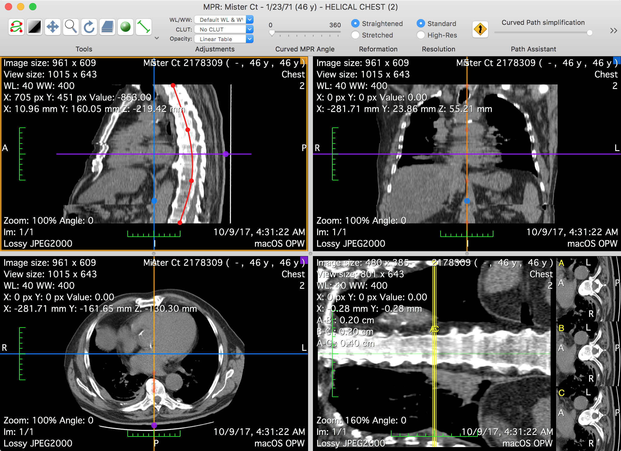
Graphical User Interface
The main purpose of this window is to allow you to define the path that is used, along with the angle, to define the reconstructed plane.
The viewer is split into four views. Three of these are actually a 3D MPR viewer: their purpose is to facilitate the navigation of the dataset, so that you can more easily position the CPR path. The resulting reconstruction is displayed in the fourth view.
The Toolbar
The viewer toolbar provides access to tools and functions that interact with the displayed dataset or with the viewer interface.
This toolbar can be customized just like the database window toolbar, but with other available items, which are reviewed in this section.
Tools
You can use this item to choose the mouse interaction effect for the left mouse button. By clicking on one of these buttons, you select the corresponding tool.
The following tools are available: Path, WL/WW, Pan, Zoom, Rotate, Scroll and Revolve; the additional ROI tools are: Length, Angle, Rectangle, Oval, Text, Arrow, Open and Closed Polygon, Pencil, Point and Brush. The ROI tool button function changes through the pop-up button on the right side.
Adjustments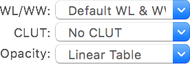
Through this item you define how to display the slice data. You may adjust the used WL/WW, CLUT and opacity table: just like in the 2D viewer, the presented pop-up buttons list the available presets.
Angle
This item allows you to set the orientation of the reconstruction by defining its angle.
Reformation
The reformation parameter defines how the dataset is projected onto the reconstruction: when straightened, the CPR path will appear as a line; when stretched, its curves are preserved, projected on a CPR plane with its centerline defined by the path's first and last points.
Resolution
This item allows you to specify the level of detail used to render the displayed slices.
Path Assistant
The path assistant tries to define a path from the two input points. It uses an automated path-finding algorithm to add intermediate points that follow the anatomy in the dataset. The input points should be the two extremes.
The path simplification slider allows you to simplify the resulting path.
Path Mode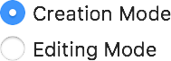
This item defines the behavior of the path tool. In editing mode, your clicks won't result in extra path points being created.
Views
These buttons allow you to reorganize the layout of the views.
Thick Slab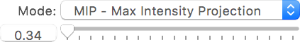
You can use this item to redefine the thickness of the rendered slices, and their rendering mode. The thickness is defined in millimeters, displayed in the lower left field. It can be adjusted using the lower right slider.
The available rendering modes are the following: maximum intensity projection, minimum intensity projection and mean intensity projection.
Reset
This button allows you to reset the display adjustments to the their initial state.
Export
This button allows you to store the current reconstruction as a new DICOM series. A dedicated interface is displayed so you can set several options for the dataset creation: a series name, the image size, the quality, what views to export, what range to export and more.
Curved Path
Axis Colors
Axes
CPR Axes
Mouse Position
Sync Zoom
Interpolation